Voice Tab
- Click the
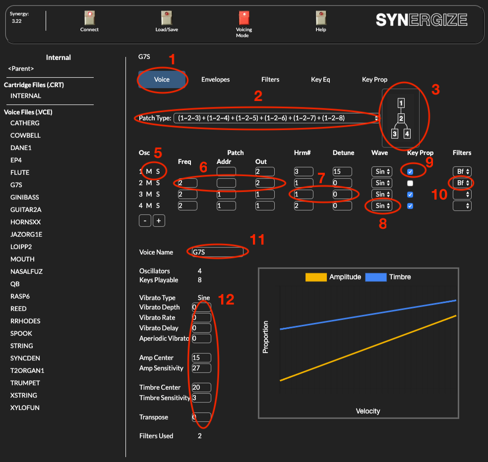
Voicetab to select the Voice editor. This is the default view when a new voice is loaded. - The
Patch Typeselector allows you to quickly change between the various factory patch types (see below). - The routing of the patch is displayed graphically (see below).
- The oscillator table contains oscillator specific settings, one oscillator per row.
- The
M(mute) andS(solo) buttons control whether the corresponding oscillator can be heard. When muted, that oscillator’s behavior is silenced. When soloed, all other oscillators are silenced (unless also soloed). - Patch Routing DSR’s. This is the low-level control over the frequency modulation and amplitude summing behavior of the oscillator interaction. These values are set when you change a patch type with the
Patch Typeselector, but you can override those settings by altering individual registers here. See below. Hrm#is the Harmonic frequency offset andDetuneis the fine-grained frequency detuning. See below.Waveallows you to select the wave type.Key Propallows you to select whether the oscillator’s behavior is altered by the Key Proportionality curve.Filtersselects which filter, if any, is used for this oscillator.Voice Nameallows you to change the “name” of the voice. Unlike in SYNHCS, the name does not have to match the VCE filename you save it to.Vibrato Type,DepthandDelayandAperiotic Vibrato,AmpandTimbreCenter,SensitivityandTransposecontrol the default values for the corresponding parameters. These will be overridable at performance time via the controls on the front panel of the Synergy. See note about performance params below.- The Amplitude/Timbre graph recreates the center/sensitivty curves as displayed in SYNHCS and the original voice library .DOC files.
The non-editable values (Oscillators, Keys Playable, Vibrato Type, Filters Used) are computed based on other parameter values.
Oscillators
There are 32 oscillators in this system, however each voice always uses them in pairs. One “oscillator” on the voice tab uses two hardware oscillators – one controlled by the “low” envelope setting, the other controlled by the “up” envelope setting. The sound created by the oscillator is interpolated between the two settings based on the keyboard velocity.
Oscillators consist of either SINE or modified TRIANGLE waveforms. If you use 2 oscillators per key to make a voice, you will have 16 playable keys. If you use 4 oscillators per voice, you will have 8 keys playable. If you use 3 oscillators per voice, you will have 10 keys playable with 2 left over.
The more complex the voice is, the more oscillators will be required.
Each oscillator can be used in three ways: to be heard, to be summed with another one, or as a modulator to another. This is shown in the patch display, which indicates how the oscillator is being used in a particular voice patch.
Patch Type
The “patch type” is selectable on the Voice Tab. It contains various ways to patch of oscillators. Synergize displays the factory patch types with both the textual format used in SYNHCS and a graphical format similar to a Yamaha’s DX7 “algorithm” graphic.
Display format
The display shows each oscillator in the voice. A line between them means the oscillator(s) above it frequency modulate the one below. Oscillators on the very bottom row are audible. Oscillators on rows above are modulators for other oscillators. When more than one oscillator modulates another oscillator, the modulating oscillator’s outputs are summed, then the resulting signal is used to modulate the target oscillator.
For example in the standard patch 4: Oscillator 1 modulates Oscillator 2. Oscillator 3 is summed with that and the sum modulates oscillator 4. Similarly for oscillators 5 through 8. The output of oscillators 4 and 8 are audible:
SYNHCS used a textual representation of this modulation routing. A ~ indicates “modulation”, a + indicates summation (“additive”):
(1~2+3)~4) + ((5~6+7)~8)
The actual routing is controlled by a set of three values on each oscillator: the Freq, Adder and Output registers. These are described below.
Standard Patch Routing
-
PATCH #1,
1 + 2 + 3 + 4 + 5 + 6 + 7 + 8, represents additive synthesis. Each oscillator has values which are “heard” as they occur. It is the most accurate form of synthesis, but requires a larger number of oscillators to attain results.
-
PATCH #2,
(1~2) + (3~4) + (5~6) + (7~8), is used in sets of 2 oscillators at a time. Number 1 uses its parameters to “modulate” number 2 which is listened to. Number 3 modulates 4 which is listened to etc. This modulation sets up a predictable array of sonic qualities , which helps to provide rich sonorities , aiding in the conservation of oscillators. This modulation is actually called PHASE MODULATION and CANCELLATION , not to be confused with Frequency Modulation as used in some Synthesis techniques.
-
PATCHES #3-10 are various combinations of one oscillator modulating another, and in many cases mixing the modulation results with some additive synthesis techniques. This makes the synthesis process very unique and full of possibilities:
-
((1+2+3)~4) + ((5+6+7)~8)
-
(1~2+3)~4) + ((5~6+7)~8) -
(1~2) + 3 + 4 + (5~6) + 7 + 8
-
((1+2)~3) + ((1+2)~4) + ((5+6)~7) + ((5+6)~8)
-
(1~2) + (1~3) + (1~4) + (1~5) + (1~6) + (1~7) + (1~8)
-
(1~2~3) + (1~2~4) + (1~2~5) + (1~2~6) + (1~2~7) + (1~2~8)
-
(1~2~3~4) + (1~2~3~5) + (1~2~3~6) + (1~2~3~7) + (1~2~3~8)
-
((1~2+3)~4) + ((1~2+3)~5) + ((1~2+3)~6) + ((1~2+3)~7) + ((1~2+3)~8)
-
These patches are changable from the Synergize Voice Tab via the Patch Type selector, or by directly editing any of the oscillator patch registers. By selecting register combinations that don’t match the factory defaults, you can create unique and custom modulation schemes.
The conclusion and concept is that the GDS has the accuracy: of additive synthesis, and the conservation of combinational forms of synthesis as needed for certain sounds.
Patch Registers
The synthesizer circuit is a time multiplexed microprocessor controlled digital oscillator which provides the user with 32 independent audio oscillator functions. Each oscillator function also includes a frequency ramp generator, an amplitude ramp generator, and a timer. A patching network is provided allowing each oscillator to receive additive and/or frequency offset inputs from other oscillator’s outputs.
The oscillator output is a series of samples or numbers (32,000 per second) which represents the synthesized sound. All of the synthesis, amplitude control, and sound mixing is done while the sound is represented digitally by the series of samples. The changing analog voltage needed to represent the audio external of the systhesizer is generated by a 16 bit digital-to-analog converter (D/A) acting upon this series of samples.
Actually, only one high speed oscillator circuit is used, and is time multiplexed 32 ways in order to generate the multiple oscillator functions. Each oscillator function uses 11 registers for control.
The oscillator circuit performs all of the calculations necessary to generate one sample of an oscillator output in about 1 usec. A final output sample is required only every 32 usec. for each channel. Each 1 usec calculation period is called a “time slot”, and these are numbered 0, 1, 2, …, 31. The output of oscillator number 0 is calculated during time slot 0, the output of oscillator number 1 is calculated during time slot 1, etc., until the output of oscillator number 31 is calculated during time slot 31. It is the completion of oscillator number 31 that initiates a D/A converter cycle.
Each oscillator has two inputs that may receive data from the outputs of other oscillators. One of these is the frequency offset (“Freq”) input used to produce vibrato or “voicing” effects. The second is the “Adder” input which is used to combine the output of some other oscillator with the output of the current oscillator. Four temporary data storage registers (DSR) are provided to receive this combined output as well as supply the data for the two types of oscillator inputs.
The oscillators may be interconnected using the DSRs, as specified by the control bytes. One oscillator output may be used to frequency modulate another oscillator, and the output of this oscillator added to the output of another, etc. The calculation proceeds sequentially (i.e. 0, 1, …, 31) with the current oscillator’s output available to any later calculated oscillator
Four data storage registers (DSR) are available to pass oscillator outputs to to the inputs of other oscillators. The “PATCH” control byte contains three fields to specify which of these registers is used for the FM input, adder input, and output.
NOTE: Only 2 of the 4 registers are available for user-level patching; the Synergy reserves 2 of the 4 for internal use.
The value of the Freq register is used to shift the frequency of the oscillator.
Since each DSR may be used several times during each sample period to pass data between oscillators, almost any interconnection between oscillators may be accomplished. However, care must be taken to assign the oscillators in the proper order. For a group of oscillators interconnected, the lowest numbered oscillator should be assigned to produce the signal needed earliest in the calculation.
Note that the output of oscillator 31 may be used as an input to oscillator 0 or a later calculated oscillator.
Harmonics and Detune
HARMONIC values can be assigned to any oscillator, no matter how it is used. In addition to the standard harmonic series from 1 (the fundamental) through the 30th harmonic, “s” harmonics are possible, 1s,2s,3s, etc. These represent the Semi-tones that would exist between the fundamental and 2nd harmonics. Access to them is especially useful in modulation applications and very useful in helping to produce “unmusical” qualities in sounds such as breath, bow scratch and lip buzz.
Harmonics do not necessarily have to be in tune. In most acoustic instruments they are often not in tune, or are fluctuating under different playing activities. Therefore DETUNING of harmonics can be accomplished roughly 1/30hz at a time. Additionally, degrees of random detuning fluctuations are possible per oscillator. This is useful for many chorusing and imperfect treatments.
Note about performance parameters
Due to the way Synergize interacts with the Synergy in voicing mode, the Vibrato Type, Depth and Delay and Aperiotic Vibrato, Amp and Timbre Center, Sensitivity and Transpose can be edited both from the Synergize application and also from the corresponding switches and knobs on the front panel of the Synergy. The connection between Synergize and the Synergy is not bi-directional during the editing process. If a value is changed in Synergize, it is transmitted to the Synergy, but if the value is changed on the Synergy, the value is not transmitted to Synergize in real time.
When you save the voice, Synergize retrieves the actual state of the settings from the Synergy. If parameters were edited via the Synergy front panel, those are the values stored in the VCE file.